Alternative Elevator
Control System for F3A models
By Troy Newman updated***7/2004
The following information is provided as a How to Article,
nothing more. I am presenting it as a result of requests by other modelers to
see the method. The author assumes no responsibility for any failures of the
method show. I have used this method now for a long time and no failures. The
installation and the attention to details are critical in the trouble free
operation of this setup. In essence we are dealing with glue joints, and builder
manufactured components. Its up to the builder to take every precaution he feels
needed and assumes all risk of the operation. Read these instructions entirely
before you dive into building this thing. There are some options given later in
the directions that may fit your needs better and your choices early on will
restrict you options later. I give the method I use. You can adapt this to
anything you like.
In my opinion the absolute best elevator control assembly
is designed to be light, strong, and allow the least amount of differential
between the elevator halves. The following setup is not my design, but I have
adapted a couple of different methods of mounting to insure that the best
solution for me. I have done this same setup on 6 planes and just finished it on
a 7th. Since 1999 I have been running this setup in F3A aircraft with
hundreds of flight a year and zero failures and zero maintenance. You can also
with careful install put this in a model that is already done and painted.
In comparison to this I have a couple other systems to
address and why I don’t use them. I will only deal with single servo
applications because I like a single servo. Any of these setups including the MK
Bellcrank can be driven with 2 servos. Two servos give a weight penalty not only
in the servo but the extension wire. You would be surprised at how much a 1
meter extension weighs. There is also the issue of matching the servo travels.
This has become almost a non-issue with today’s digital servos. I know several
top flyers using the JR 3421 digitals one on each elevator. These are great and
provide a good solid connection. Since they are digital the centering and the
holding power make them perfect in the dual application. I found I liked a
single servo better!
Cables, Pull-Pull
First of all many people like
cables it’s a pull-pull setup and its very light. Another big advantage to
cables is the fact that it is infinitely adjustable. You are not 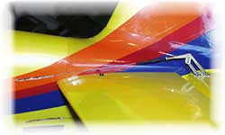 limited
by the 1 turn of a 2-56 thread in adjustment. If done properly the connection is
solid and feel is great. The next plus for cables is the fact that you can tune
all 4 travels of the elevator exactly the same throw at the end points. This can
be done easily using the length of the control horns and comes out dead on.
limited
by the 1 turn of a 2-56 thread in adjustment. If done properly the connection is
solid and feel is great. The next plus for cables is the fact that you can tune
all 4 travels of the elevator exactly the same throw at the end points. This can
be done easily using the length of the control horns and comes out dead on.
I have not used the Kevlar type
cable setups. I choose 30-40lb test nylon coated steel fishing line from the
fishing shop. It comes in 30ft rolls for about $2 and the little crimpers are
about the same $2 a pack. You can do many many planes with this $4 purchase. Now
for a Cable type system to be effective in a model you have to make sure that
the line is absolutely a straight line from servo to the control horn. This
means exits in the fuse must no touch the cable and be totally free of any
friction. Anything touching the cable will cause it to fray and fail.. You also
have control horns on top and bottom of the surface. This is pretty easy since
most people choose a 6-32 bolt as the control horn. So you just leave it run
through and attach top and bottom.
Cables have many good sides, but
here are my downsides. It doesn’t look as clean and as neat. Function before
form this is OK. Also you have to make absolutely sure the cable is no riding on
anything inside the fuse like the fuse exits. This will cause the cable to fail
early in its life. I have had some cable failures not many and not recently but
they have failed. The key here I think is using eyelets rather than rigging
couplers. The eyelets allow the cable to loop around the connection rather than
kink. The kink will cause a failure. SO
in this case it is again not as clean and neat a setup.
The tension of the cables is critical. If too tight it will “pop”
into place and cause grief with your servo trying to center and also causes side
loads on the servo shaft.. While too slack of a cable will cause a mushy feel. I
have found that as the cable ages with the loads we apply they will stretch
slightly and become loose. So another drawback is the fact that you have to keep
checking them and make sure the tension stays constant. I know how we measure
cable tension in the mechanical engineering world, one way is to deflect it
(push in the middle) and measure the distance it deflects. But what is a good
number? The other problem is that the cable could be stretching under loads.
Since there is a cable going to each of the elevators top and bottom you are
stuck with 4 different cables with possible different lengths all be them small
differences. You also have 4 sets of connections that are not done exactly the
same in the same spots. This can affect the stretch and you can get different
tensions on all 4 cables. So you can get differential in theory based on the
material and the methods used to secure the cables. I want those elevators going
up together no matter if I have huge loads on them or not.
This says I will bank the cables
and look for better ways. I want the best solution and cables may be it for me
but lets look further. Not only that but the cleaner looks are important to me.
I always have trouble getting the exit hole right on the cables, and this
becomes critical. A sure fire way to make it right is to have the hole
oversized. This affects the looks. Personal Preference!
MK bellcrank method
The MK bellcrank is a wonderful little device. Ball bearing
sockets make the transfer of forces friction free. It works well. But you have
to abide by some rules. You must use a
 stiff
pushrod to serve the middle. I recommend CF pushrod like sold by Central Hobbies
with the titanium ends. These get used for the pushrod devices both serving the
middle of the MK and as the outputs to the Elevators. I choose the 5/32” rod
for the output rods and the 3/16” for the input rod. This works very well.
Another thing is support the input pushrod or have a very short run at it.
Otherwise the loads could cause this to bend and the solid connection will not
be there under large loads. At least in theory the two sides will deflect the
same amount as the rod in the middle bends slightly so you should be good to go.
Then you have lots of connectors. Some guys have converted the Mk to cables
pull-pull inside the fuse and pushrods outside to the elevators. This is in my
opinion not the best of solutions because you have no way to watch those cables
to look for wear and you are getting the same tension issues as before. Next is
the device is made of plastic, however strong that maybe it does flex a little.
So when using your ball links and stuff don’t use the standoffs this will make
the connection have a moment arm larger and will cause the arms to flex even
more. It would be a great little thing if it was aluminum but the price would be
higher. Also you need to use ball bearing connectors everywhere. This insures
free flow of all the connections and eliminates the friction in the system. You
need a total of 6 connectors, which means using the top of the line MK stuff
with the ball bearings for the best setup you have about $8 per connector for a
total of $48 in connectors. Add in the price of the CF pushrods with all the
titanium ends. Say it is another $25-30. Remember there are 3 separate pushrods
you have to setup. This combined with the $30 for the Bellcrank itself means you
have a $100 elevator setup. Now some people choose the Fiberglass DB pushrods.
They are black and some guys are convinced they are CF and they are less
expensive than the Central Hobbies CF ones baby. Well I have used them in the
past and the ones I have had including the black ones are not CF rather they are
black colored fiberglass arrow shafts. They also weigh more than the Central
Hobby stuff and not nearly as rigid. So I use them on 60 sized sport stuff. The
$100 setup is a bit pricey but will work superbly if installed right. You will
never feel the elevators getting differential even though when you flex them
with you hands you can make differential. I guess our flight loads are lower
than my greasy palms. This entire $100 setup also has a weight to it. I don’t
mind weight because it’s needed for strength but have to watch for excessive
weight gains. I weighed all the MK stuff including the support plates in the
fuse the screws to install it and all the pushrods made up with the connectors.
The weight was 4ozs this seems high to me.
Now I used the MK device for a couple of years and felt it was the way to
go. I had nothing better at the time so it was the best solution. But its weight
was a killer and so was the price tag. So I banked it for another option.
stiff
pushrod to serve the middle. I recommend CF pushrod like sold by Central Hobbies
with the titanium ends. These get used for the pushrod devices both serving the
middle of the MK and as the outputs to the Elevators. I choose the 5/32” rod
for the output rods and the 3/16” for the input rod. This works very well.
Another thing is support the input pushrod or have a very short run at it.
Otherwise the loads could cause this to bend and the solid connection will not
be there under large loads. At least in theory the two sides will deflect the
same amount as the rod in the middle bends slightly so you should be good to go.
Then you have lots of connectors. Some guys have converted the Mk to cables
pull-pull inside the fuse and pushrods outside to the elevators. This is in my
opinion not the best of solutions because you have no way to watch those cables
to look for wear and you are getting the same tension issues as before. Next is
the device is made of plastic, however strong that maybe it does flex a little.
So when using your ball links and stuff don’t use the standoffs this will make
the connection have a moment arm larger and will cause the arms to flex even
more. It would be a great little thing if it was aluminum but the price would be
higher. Also you need to use ball bearing connectors everywhere. This insures
free flow of all the connections and eliminates the friction in the system. You
need a total of 6 connectors, which means using the top of the line MK stuff
with the ball bearings for the best setup you have about $8 per connector for a
total of $48 in connectors. Add in the price of the CF pushrods with all the
titanium ends. Say it is another $25-30. Remember there are 3 separate pushrods
you have to setup. This combined with the $30 for the Bellcrank itself means you
have a $100 elevator setup. Now some people choose the Fiberglass DB pushrods.
They are black and some guys are convinced they are CF and they are less
expensive than the Central Hobbies CF ones baby. Well I have used them in the
past and the ones I have had including the black ones are not CF rather they are
black colored fiberglass arrow shafts. They also weigh more than the Central
Hobby stuff and not nearly as rigid. So I use them on 60 sized sport stuff. The
$100 setup is a bit pricey but will work superbly if installed right. You will
never feel the elevators getting differential even though when you flex them
with you hands you can make differential. I guess our flight loads are lower
than my greasy palms. This entire $100 setup also has a weight to it. I don’t
mind weight because it’s needed for strength but have to watch for excessive
weight gains. I weighed all the MK stuff including the support plates in the
fuse the screws to install it and all the pushrods made up with the connectors.
The weight was 4ozs this seems high to me.
Now I used the MK device for a couple of years and felt it was the way to
go. I had nothing better at the time so it was the best solution. But its weight
was a killer and so was the price tag. So I banked it for another option.
My Preferred Method
Now the long awaited method I use. This came to me from
Scott Anderson of Dynamic Aircraft. Scott is a master builder and has built
championship level airplanes for many of the top guys. Scott also builds TOC
aircraft. His work is among the best that I have ever seen. The work is light,
strong, and detailed. From what I understand Scott got the idea from a long time
pattern flyer Tony Frakowiak. So I want to give as much credit for this idea
away. It works great. This method requires much more work to install than the MK
or the cables. And it takes doing it at least once to learn the technique of
installing it in the fuse. But the second time its cake and you need only line
up your servo and your exit holes. The pushrod setup then spans the gap. The
extra work is intimidating and can make you stare at it for hours thinking about
how it is suppose to work. But when done it is lighter than the MK. Only 2ozs,
and its stiffer in the differential category too. Totally mechanical, and if
installed properly is friction free. I have some pictures below that show it
completed….So you should not have that much head scratching
First of all the basic layout is (2) solid Carbon Fiber
rods running the length of the fuse to each elevator. These are solid rods not
hollow….They are 0.070” diameter or the same size as a 2-56 pushrod. So they
are pretty small. These rods are available from Central Hobbies as the D.E.P.S.
kit Dual Elevator Pushrod rod kit. It comes with all of the fitting and little stuff you need. In the past I have
purchased all this stuff separately from various sources. Now it is all packed
as a kit. These can be found at www.centralhobbies.com
Ok getting started, you wrap sewing thread around the balsa
stick and the plastic housing with the CF pushrod inside of it.
Now don’t warp it too tight as the plastic will pinch the rod inside
and cause more friction. So your goal is to get the plastic housing attached to
the balsa stick. Do this for each pushrod. The wrap is done like a fishing pole
with close together wraps for about an inch or 2 then looser for 2-3 inches then
tighter wraps then looser. All the time keeping just enough tension in the
thread to keep the Pushrod attached to the balsa stick and no more. Once this is
done you hit the sewing thread with thin CA glue. The balsa will soak it up like
mad and will stiffen. This is why a softer piece of balsa will work. You don’t
need to get all of it just make sure that the thread and the pushrod are not
moving on the balsa stick and there is no way for it to come off. These sticks
don’t move and are glued into the fuse as the guides for the CF rods inside
the tubes.
Now this is where I vary from the designer’s idea a
little bit. I measure the length required to build a ladder from the front
mounted Elevator servo to the exit holes in the fuse.
I build a ladder type structure attaching the pushrod assemblies to each
other. This is done in a big “V” with
the Plastic housings on the outside
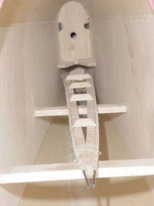
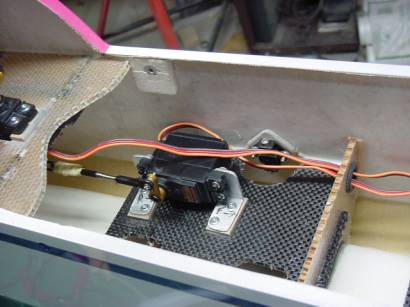
of the “V”. See the attached picture #1 of the inside.
Picture #1 Ladder built and glued inside the fuselage. The
horizontal Balsa former above the ladder is part of the stab install. You should
have your stab installed already before you install this pushrod setup. I leave
the tail post open so I can get in there and work. But the Stab is 100%
installed. I use removable stabs but glued in solid stabs are fine also…The
pushrod doesn’t care. The
Vertical former with the hole in the middle is located in the fuse ahead of the
stab slightly and keeps the fuselage from twisting in front of the stab. This
former also keeps the fuse sides from flexing ahead of the stab and causes the
fin to be much stiffer also.
The “V” is the width of the fuse at the exit
holes…pretty easy dimension to get. Let the Plastic
guide and the pushrod overhang the balsa sticks a bit. They will exit the
fuse and you want that plastic guide to be cut flush with the fuse sides making
a friction free guide the entire length while inside the fuse. I use ¼ sq balsa
for the cross pieces of the ladder. I build the “V’ up and glue it all with
thin CA. Then take some ¼ balsa, light stuff say ¼” x ¾”, and make the
supports that you see holding it in position in the fuse. Leave the assembly
about 3” short of the Elevator Servo connection. The reason is you have to
attach the pushrods to each other, and you have to have some sort of connector
to attach to the servo arm. I’ll
discuss the attachment to the servo later.
IMPORTANT:
For a friction free setup the pushrods cannot have any
bowing or bending from the fuse exit to the elevator control horn, or from the
center of the fuse connection shown above to the servo arm. So it is very
important to locate your fuse exits in the perfect location. I usually have my
stabs done and completed. The stab mounted on the fuse and the control horns
already on the elevator halves so I know the proper location. You also should
have your elevator servo mount and servo with arm installed so that the angle of
the ladder is perfectly setup as a straight shot inside the fuse. This is the
most critical and most difficult of the install. Make your fuse exits slightly
oversized to allow for a perfect location. Once you have the locations and
everything trial fit, you’re ready to make the cross supports to hold the
ladder inside the fuse. Oversized is good then sand them to fit further down the
back of the fuse if needed. These are easy to make and need not be perfectly
placed. Just make sure you are close to mid span and attached up front near the
servo. The ¼” square balsa sticks with the Plastic
sleeves attached are continued all the way back to the exit holes and
actually glue to the fuse at this location. This gives a really solid support
where the rods exit the fuse. This method gives 3 supports over the entire
length of the pushrods while inside the fuse. Again refer to the picture #1
above for the installed setup. You can use more supports but its not needed. I
would not use less supports than the 3 shown above..
One other note when cutting off the balsa sticks for proper
length leave the Plastic sleeve and
the CF pushrods alone and leave them really long. This will aid in future steps
and setup.
When you have the ladder glued into the fuse, use extra
epoxy with Micro balloons to fill the slot at the rear of the fuse for the
pushrod guide exits. This makes them solid and you can cut the Plastic
guides and sand flush with the side of the fuse. Idea here is just to
make sure the Plastic tubing is totally surrounded or incased in Epoxy. You are not
trying to fill the slot for painting just make sure that the Plastic
sleeve is not going anywhere. Cut and sand the Plastic
and any epoxy flush to the fuse side. Dips and depressions should be
filled before primer and paint using lightweight auto body filler. I use
Polyester glazing putty…Dries very quick and sands like balsa. Make sure to
keep the Plastic sleeves clear of epoxy or filling putty.
Then you are ready to paint the fuse. Don’t use any
special prep to your fuse exits and don’t worry about primer or paint clogging
them up. Plastic is smooth and
nothing sticks to it, not even your eggs. So when you’re done the little paint
that gets inside will come right out.
Fuse is all done painted and its time to hook everything
up.
Servo connection up front.
There are a couple variations on this connection and
everybody I talk with about the connection has a different take. The first setup
and the original design I copied was the ladder was straight, meaning the two
sticks were parallel. The CF pushrods that you see in the picture #1 above were
then attached to the fittings (I’ll show the fittings and discuss them later
when doing the elevator horn connections) and then a piece of Plywood, maple, or
even Aluminum was used to get the two sides tied together. This way only one
servo would drive the cross bar and the two longer pushrods were follow. This
setup of the parallel sticks works best for the absolute friction free setup.
The “V” like I use is a little tougher to install but is lighter, and has
less hardware and connections. If you install it right the result is just as
friction free but tougher to measure everything and setup. The parallel sticks
are just cut to length after they are fitted. The “V” requires more work on
the setup and assembly of the ladder. Either way works well. Of course the
parallel setup can also offer a dual elevator servo option. This allows the
servos to be upfront and not affect the balance of the plane. Again I would only
use digital servos on a dual elevator setup. The “V” setup can also allow
you to use one servo but connect the two separate CF rods to the servo arm. One
on top of the arm and one on the bottom with a single bolt going through the
ball links. This is a good choice but requires a very good setup and a little
more time in the layout and building of the ladder, as both sides need to be
exactly the same since they are running to the servo independently.
I use the following method its light, simple and has
survived crashes still intact. I use a piece of Central Hobbies 5/32” Carbon
fiber pushrod about 3” long and attach it to the Two 0.070” solid CF rods
with Kevlar thread and thin CA. I wrap about 1” of length. The 4-40 Titanium
fitting below is not glued in place yet just sitting to show the connection for
clarification purposes. The 4-40 fitting gets glue in place later on….
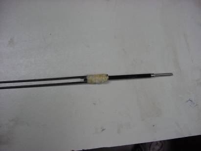
Picture #2 (2)
0.070” solid CF rods attached with Kevlar thread and thin CA glue to a Central
Hobbies 5/32” hollow CF tube. The 0.070” rods are still 48” long and the
5/32” pushrod tube is about 3 inches long.
Leave the 5/32” hollow CF tube long for now. Get the
servo 100% mounted and ready for action. It really will not matter whether it is
mounted on its side or not. I choose a side-mounted setup as shown in a later
picture. But the fact is it really is of no consequence.
Trial fit the pushrods in the sleeves. You may need to
clean out the paint that is in the Plastic sleeve. This will usually just pop right out when you slide
the pushrods in. If not. Use a small rat-tail file to open the exit up until its
friction free again.
Leave the elevator horn connection alone for now. The
pushrods are long and need to have one connection setup perfectly before you go
to the other end.
Make sure that you have about 1” of travel each way out
of the servo while pushing the “Y” pushrod. Its important there is no
binding of the “Y” as the separate rods enter their respective Plastic
sleeves. Its OK to have a little extra of the dual pushrods extending out
past the balsa sticks and Plastic sleeves
but don’t make it a really long run. These rods can flex a little so keep
everything as close as possible but still allowing for friction free movement.
Cut the length of the 5/32” Central Hobbies pushrod off until everything is
the proper length. Remember you have a ball link and a Titanium end to glue into
the now single side of the “Y” connection.
The way I do this is to test fit everything together. I actually thread
my ball link onto the Titanium fitting and slide the fitting into the Hollow CF
tube. Everything is attached to the servo arm and the Elevator servo powered up
and centered. I then move the servo its maximum amount of expected travel and
look for binding. I make sure I have just a little extra travel room in case
needs change in the future and I need more elevator throw than expected. Once
all the parts are dry fit and assembled make sure everything is the proper
length. If all is correct epoxy the
Titanium end into the 5/32” piece of Hollow CF pushrod. I use 30 min Epoxy and
make sure I have a good lather of it inside the Hollow pushrod. Wipe any excess
of with paper towel. While the glue is all still wet I hook everything back up
to the servo just as if it was ready to fly on this end of the pushrod. These
connections will hold everything in place while it cures.
Elevator Control Horn connections
Only after the 30 min epoxy is cured. Go to the elevator
side of the connection.
On the Elevator side of these pushrods you now have the
0.070” solid CF rods sticking out about 10-12” past where they need to be.
You are going to cut them and attach a external Titanium pushrod end.
Now use the same technique as up front. Install the solder
links whether they are the stainless or the brass versions onto the clevis.
Install the clevis on the elevator control horn. Once this is all connected just as it will be in flight. Turn
your Elevator servo back on and make sure it’s centered. Use masking tape to
hold the elevator halves centered, mark the location to cut the 0.070” solid
CF rods. Use a Dremel cut off wheel
and cut the rods slightly longer. Now test fit everything together trimming the
CF rods back until they fit perfectly inside the solder link but have no gaps
inside the connection. Clean the CF pushrod with alcohol and take some 100 grit
sand paper and just scruff it up a little...not too much as you will cut the
Fibers and make the pushrod weak. Just scuff it lightly. Now use 30 min epoxy to
glue the pushrod inside the solder link. Make sure you have a really good lather
of epoxy inside the hole and good coverage. Once all in and covered good with
glue, wipe any excess epoxy off the connection from the outside. Leave a small
bead of glue at the joint. It should look a little like a Plumbers sweat joint.
Let everything cure!…..and its all done and connected.
If you make a mistake and the lengths are not correct. You
can remove the pushrod ends and re-install them. To change the fittings, remove
the clevis from the fitting. Take a Bic lighter and hold it under the fitting to
heat it up. Once hot, the epoxy will be liquid, take a pair of pliers and just
slide it off. The epoxy will soften with the heat and the fitting will slide
right off. Clean the old epoxy off while still soft using 100 grit sand paper
and then follow the steps above the re-install a new fitting.
The finished product looks like Picture #3 showing
the elevator servo connection. The picture below shows a JR 8417 digital servo
side mounted. The Servo arm is the Hangar 9 Aluminum Servo arm part #HAN3431.
This is the part number for the JR servos. The Ball link is a Hangar 9
4-40 threaded ball link with a 2mm screw
going through the servo arm. The Titanium fitting going into the CF pushrod is
the 4-40 fitting for the 5/32” Central Hobbies Pushrod.
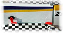
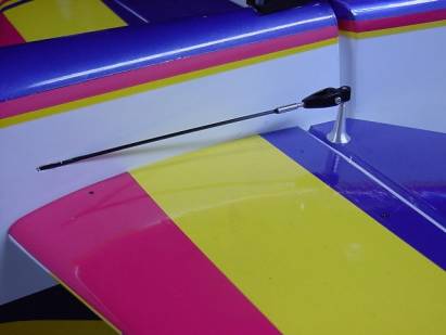
And Picture #4 is the Elevator Horn connection side. This
picture shows the MK medium Aluminum control horn, and the MK 2mm ball Bearing
clevis. The silver link is the Titanium external pushrod end in the DEPS kit.
And the connection is 30min Zpoxy resin.
Some more info on Servo choices….
And my choice for elevator servo on a single setup is
anything with about 80-90oz-in of torque. This is overkill for sure, but You can
never have too much power. The JR 4131, or 8101 are great servos in the analog
world. They offer very good precision and a strong power curve. If you want to
“GO Digital”…I use the JR 8231, JR
8417, or the JR 8411SA. The 8411SA is a superb choice for this application. My
opinion you can never have too much servo. Especially on a F3A model you can
never say the servo is too strong or too precise. I also use the Hangar 9
Aluminum Servo arms. These are rigid and do not allow any flexing.
Now I use this system exclusively right now on F3A models
for Elevator control. Someday I might find something better. It is not the
easiest thing to build and install. But so far it’s the lightest and stiffest
connection I have seen. You have to grab the elevator halves and try to flex
them opposite of each other to really appreciate the benefits of the this
pushrod setup. As for Radio interference issues because of the CF rods, I have
had none. I Fly JR PCM “S” receivers in my F3A models and run the Antenna
inside a tube inside the fuse. I have also flown JR PPM “FM” Receivers with
no troubles. You mileage may vary but I see no issues using the CF rods in the
fuse.
Well I think this sums it up really well. Its long but
covers the bases. The opinions above are my own and do not reflect on any
business or company providing materials. Some modelers with disagree with my
methods or choices. These are my models and I make the choices. I tried to give
some of my reasons why I make the choices I do. The advice given previously is
worth exactly what you paid for it. Just that: Opinion and Advice!
Any Questions?
Troy_Newman@msn.com